Digital Transmission in Computer Networks | Line Coding

In a computer networks, data or information are transferred from one device across a network to another in the form of a signal.
Data such as human voice, audio, video, text and number to name a few needs to be converted to either an analog signal or digital signal.
In this tutorial, we would focus specifically on how to convert a digital data to a digital signal and the techniques used.
There are three techniques that can be used in digital-to-digital conversion, which are;
- Line coding
- Block coding
- Scrambling
But the most used technique is that of line coding hence, line coding is a technique which is used to convert a digital data to digital signal in other words it converts sequence of bits to digital data.
At the sending device side, digital data are encoded or altered from it plain form either as a text or any type of data into a digital signal with the help of an encoder.
As the data travels through the link or transmission line, it is decoded by a decoder so that the receiving device would understand the data sent.
Line coding schemes
There are five broad categories of line coding schemes, and they are;
- Unipolar (NRZ)
- Polar (NRZ, RZ and Biphase)
- Bipolar (AMZ, Pseudoternary)
- Multilevel (2B/IQ, 8B/6T, and 4U-PAM5)
- Multitransition (MLT - 3)
Unipolar Scheme
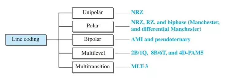
In unipolar scheme, the signal levels (or the signal voltage amplitudes) are on one side of the time axis, i.e. either on the above or below.
Basically, when you hear the word Unipolar, it depicts NRZ because NRZ (which is termed Non –Return-to-Zero) is the scheme which Unipolar is designed based on.
NRZ – Non-Return to Zero
In NRZ, the positive voltage level defines a bit of 1 and the zero voltage level defines a bit of 0.
But you might be confused, why is it called NRZ. It is called so because the signal does not return to zero at the middle or during each bit transmission.
This scheme is often or even not normally used in the transmission of data because of power consumption. For example, the power needed to transmit a bit per unit transmission line resistance is double in comparison to that of RZ in Polar scheme.
Polar scheme
In polar scheme, the voltage level of amplitude is on both side of the time axis. Instead of having a positive level and a zero or ground as in Unipolar NRZ, the polar scheme has a positive voltage level and a negative voltage level. A zero bit can be represented by a positive voltage level, while a 1 bit can be represented by a negative voltage level. There are several versions of the polar scheme which are NRZ, RZ and Biphase (Manchester and Differential Manchester).
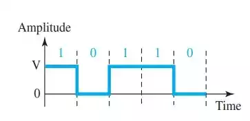
Polar NRZ
In polar NRZ, the encoding of data to signal is done with the help of two voltage levels, as we stated earlier. This NRZ scheme as two versions; NRZ – L (Non-Return-to-Zero – Level) and NRZ – I (Non-Return-to-Zero – Invert).
In NRZ – Level, the level of the voltage determines the value of the bit.
In NRZ – Invert, the change or absence of change in the level of the voltage determines the value of the bit. In other words, if there is a 0 bit occurring as the next bit, there is change in voltage level but if the next bit occurring is 1 then there is change.
Polar RZ (Return-to-Zero)
The polar NRZ discussed above has a problem, and the problem occurs when the sender and the receiver clock are not synchronized. Hence, the receiver might not know when a bit has started or ended.
That’s why RZ is here to combat that, and it is going to do so by introducing more voltage level so instead of two, it has three – a positive, negative and zero voltage level.
Also, the signal does not change after each bit, but during each bit. During each bit, it changes at the middle point and the signal goes from either a positive level to zero or a negative level to zero and stays on that zero level until the beginning of the next bit.
Now it seems as if NRZ is bad an RZ will solve the whole problem no, it does not because, it requires two signal to encode a bit and this lead to a larger bandwidth.
Biphase – Manchester and Differential Manchester
Manchester and Differential Manchester are called the Biphase encoding scheme as each combine the idea of transition at the middle of bit as in the case of RZ with that of NRZ level (for Manchester) and that of NRZ – I (for Differential Manchester).
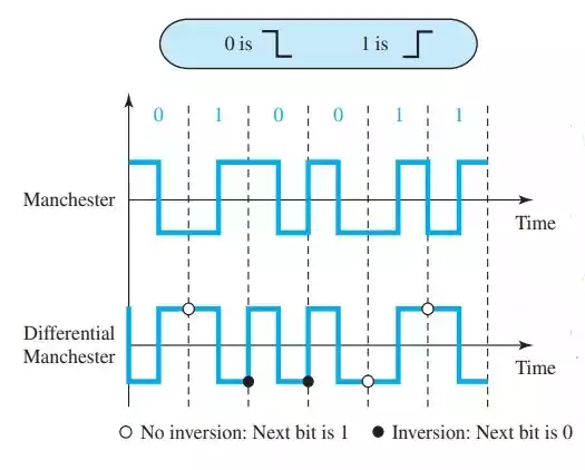
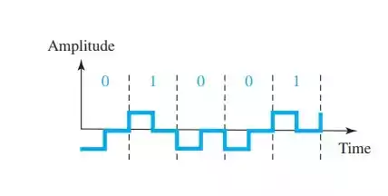
Manchester Scheme
The Manchester scheme = the idea of transition in RZ + NRZ – L. The duration of the bit is divided into two halves. The voltage remains at one level during the first half and moves to the other level in the second half.
Differential Manchester Scheme
The Differential Manchester scheme = the idea of transition in RZ + NRZ – I.
There is always a transition at the middle of the bit, but the bit values are determined at the beginning of the bit. If the next bit is 0, there is a transition; if the next bit is 1, there is no transition.
Note
Remember that the transition at the middle which is an idea of the RZ scheme is to provide synchronization for both Manchester and Differential Manchester.
Bipolar Schemes
Bipolar scheme or multilevel binary as it is sometimes called uses three voltage levels – positive, negative and zero voltage levels.
The main point about this scheme is that the voltage level for one data is at zero while for the other data element alternates between positive and negative.
There are two versions of the bipolar scheme and they are:
- AMI (Alternate Mark Inversion)
- Pseudoternary
AMI (Alternate Mark Inversion)
Bipolar AMI is the common type of the bipolar scheme. A binary zero is represented by a zero voltage level, while binary 1s are represented by an alternating positive and negative voltage levels.
That is why from the name Alternate Mark Inversion where Mark is 1 in telegraphy, hence it becomes Alternate 1 Inversion.
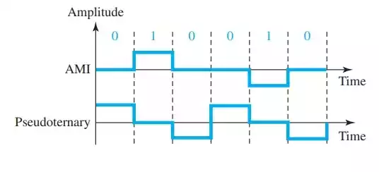
Pseudoternary
Pseudoternary is an opposite or another version of AMI whereby binary 1s is encoded as a zero voltage while binary 0s are represented by alternating positive and negative voltage levels.