How to Use (or Configure) 555 Timer as a Schmitt Trigger?
In electronics, the 555 timer is a small but mighty integrated circuit. Its versatility makes it a valuable component in various timing circuits.
One particularly interesting application of the 555 timer is using it as a Schmitt trigger.
In this article, we will look into what a Schmitt trigger is, explore the basics of the 555 timer, and learn how to configure it as a Schmitt trigger.
Table of Contents
What is a Schmitt Trigger?
A Schmitt trigger is an electronic circuit with two stable states and hysteresis. It’s designed to amplify and shape input signals so that the output transitions between two distinct voltage levels when the input reaches specific threshold levels.
This unique characteristic makes it useful for cleaning up noisy signals and generating square waves.
💡
Because, if one threshold is used (as oppose to two used in schmitt trigger) and a noisy input signal is applied at the input of a device like op-amps (Operational Amplifier) the output wont be clean, there will be some dips.
Basics of the 555 Timer
The 555 timer, formally known as the NE555 IC, is a widely used integrated circuit that can be configured in various modes.
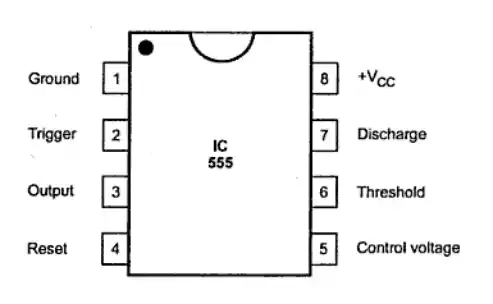
555 timer circuit block diagram
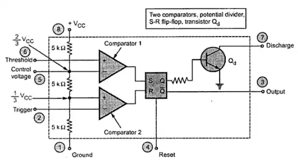
Internal block diagram of 555 timer
These modes include astable, monostable, and bistable.
a) Astable Mode
In astable mode, the 555 timer is used to create oscillating circuits. This can be useful for applications like square wave generators and pulse generators.
b) Monostable Mode
The monostable mode allows you to create one-shot pulses of a predetermined length, making it ideal for applications that require precise timing control.
c) Bistable Mode
Bistable mode transforms the 555 timer into a flip-flop or a latch, which can store a binary state.
How to Configure the 555 Timer as a Schmitt Trigger?
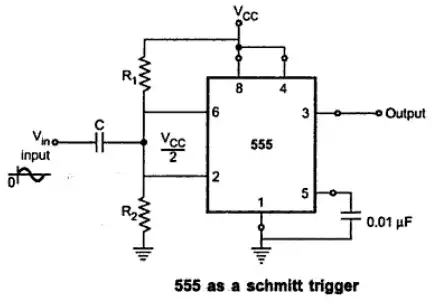
555 timer as schmitt trigger
To configure the 555 timer as a Schmitt trigger, you need to connect the trigger (pin 2) and threshold (pin 6) pins of the 555 timer together – it’s just like configuring an astable multivibrator.
This connection forms a positive feedback loop, causing the output of the 555 timer to oscillate between its high and low states.
These high and low states in 555 timer has the reference voltages 2/3 Vcc for the threshold and 1/3 Vcc for the trigger respectively.
💡
Vcc is the voltage supply of the 555 timer.
The hysteresis of the Schmitt trigger is determined by the values of the resistors connected to the trigger and threshold pins.
💡
Hysteresis represents the difference between the input voltage at which the output switches high and the input voltage at which it switches low.
A larger hysteresis makes the Schmitt trigger less sensitive to noise in the input signal.
The analog input signal is applied through a capacitor which is also connected to the trigger and threshold pin.
A resistor (R) is connected to Vcc (supply voltage of 555 timer) and to the point that connects the input signal to the trigger and threshold pin.
Another resistor (R) is also connected to the point and then to ground.
These two resistors makes the connected point (pin 2 and 6) to always have the value 1/2 Vcc (i.e., biased at half of the 555 timer supply voltage).
The pin 4 (reset pin) is connected to pin 8 (Vcc or supply voltage pin of the 555 timer) to make sure that it does not go low, thereby not force resetting the 555 timer.
When a sinusoidal input wave that has value greater than 1/6 Vcc (i.e., 2/3 Vcc - 1/2 Vcc) is applied to the circuit as input,
it causes the internal flip-flop of the 555 timer to alternately set and reset—which helps to create a clean square wave at the output.
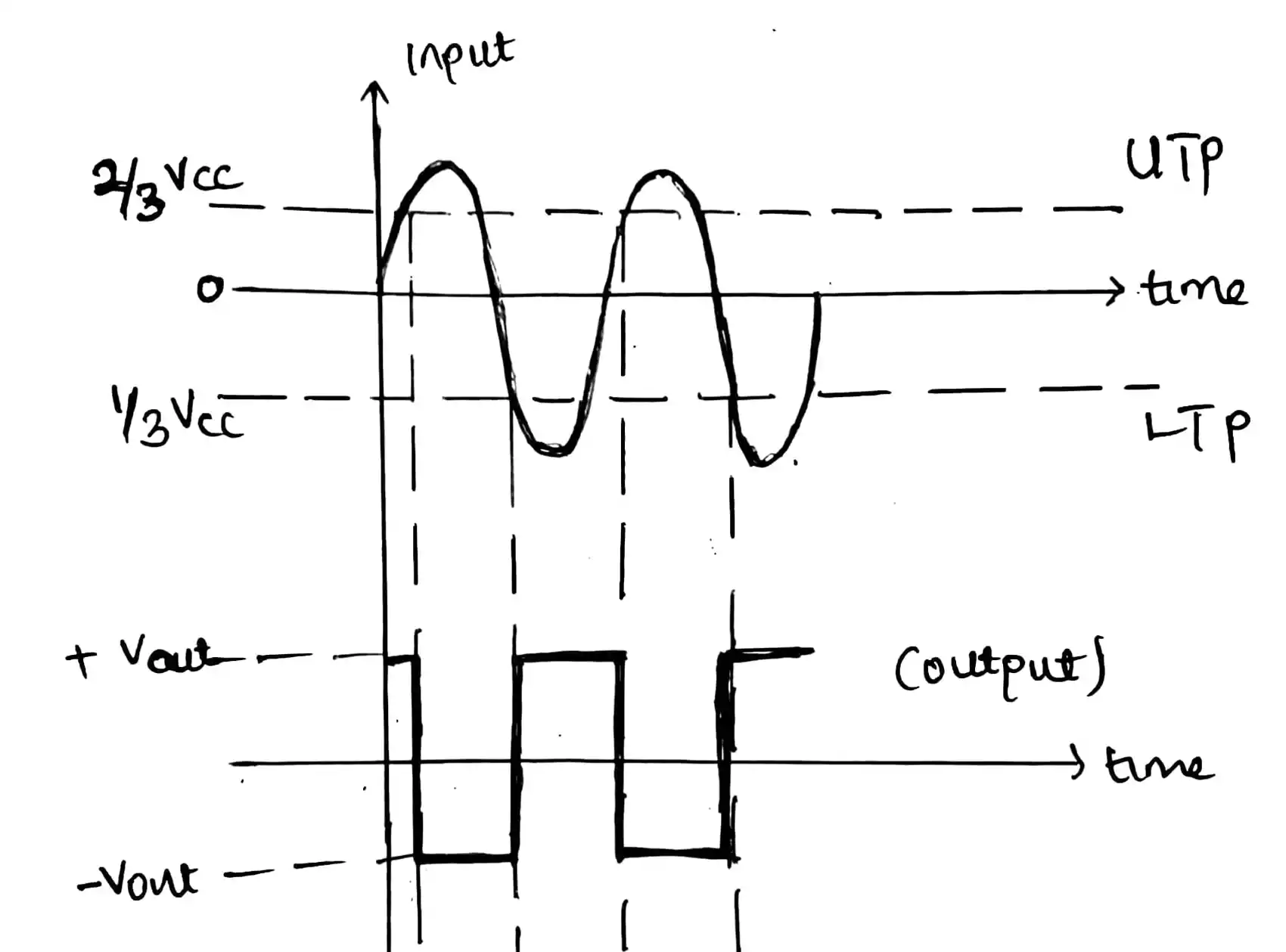
Schmitt trigger output waveform
Here is the output waveform of the Schmitt trigger.
As you can see, the input signal is sinusoidal. There are two threshold points, UTP (Upper Threshold Point) with value which is 2/3 of the Vcc and LTP (Lower Threshold Point) which is 1/3 of the Vcc.
In order to produce an output, part of sine wave that is above the UTP and below the LTP are considered because,
the part of the sine wave greater than UTP (which is 2/3 Vcc) will trigger the threshold pin of the 555 timer to SET the internal flip-flop which then makes the output of the timer circuit LOW as you can see.
But, if it reaches the part of the sine wave that is below the LTP (which is 1/3 Vcc), it will make the trigger pin (pin 2) to RESET the flip flop, making the output of the 555 timer go HIGH.
This pattern keep on happening and it creates a clean square wave.
Applications of Schmitt Triggers
Schmitt triggers have a wide range of applications, making them a valuable tool in electronics. Some common uses include:
- Debouncing switches to eliminate noise in digital systems.
- Cleaning up noisy signals by providing a stable output.
- Generating clock signals in digital circuits.
- Creating square waveforms for various applications.
- Level shifting signals when interfacing with different voltage levels.
FAQs (Frequently Asked Questions)
- Can I use any 555 timer IC for this application? Yes, most 555 timer ICs can be configured as Schmitt triggers.
- What is hysteresis, and why is it important in Schmitt triggers? Hysteresis in a Schmitt trigger defines the voltage difference between the input levels that trigger a change in the output. It’s crucial for noise tolerance and signal stability.
- What are the advantages of using a 555 timer as a Schmitt trigger over a dedicated Schmitt trigger IC? The 555 timer offers flexibility and can be easily adapted to other timing functions when needed.

