What Is Optical Amplifier and Its Types?

In long haul data transmission, transmission impairments (like attenuation or noise) takes place as signal travels through an optical fiber which results in reduction of signal strength.
In order to reduce these transmission impairments, an optical amplifier is used which helps to amplify the weak signal. But unlike a repeater (which converts an optical signal into an electrical signal, and the electrical signal is then amplified and converted back to an optical signal),
an optical amplifier directly amplifies the signal without any conversion from optical - electrical and electrical – optical. Though several optical amplifiers are developed in the 1980s but become widely used for long-haul communication in 1990s. Most optical amplifiers amplify light through stimulated emission.
Stimulated emission is a type of emission in which the emitted photon matches the original photon.
Both in energy, direction and frequency.
Generally, both amplifiers have the following characteristics
-
They amplify incident light through stimulated emission (which has been discussed earlier)
-
They are just a layer without feedback
-
Gain depends on frequency or wavelength of indent signal and the local beam intensity at any point inside the amplifier
-
All amplifiers degrade the signal to noise ratio (SNR) of the amplified signal because of spontaneous emission that adds noise to the signal during its amplification. Amplifier noise figure which can be calculated using
Fn = (SNR)in/(SNR)out Where: Fn = Amplifier noise figure (SNR)= signal-noise ratio
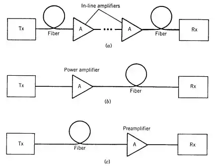
Application of optical amplifiers
-
A booster – it is placed right after the transmitting end in order to increase the optical power or signal strength of the input signal before it is launched into the transmission line. It increase distance of transmission ( up to 100km).
-
Inline amplifier – it is used for compensating the loss along the transmission line (due to attenuation induced by the fiber). It is usually used in long-haul communication system.
-
Pre-amplifier – it is placed at the end of the transmission line before the receiver in order to amplify the weak signal which enables the receiver to detect the transmitted signal. Hence, it can be said to improve receiver sensitivity.
Also, it can be used for compensating distribution losses in LANs, as it limits the number of node in a network.
Types of optical amplifiers
Optical amplifiers can be of the following types;
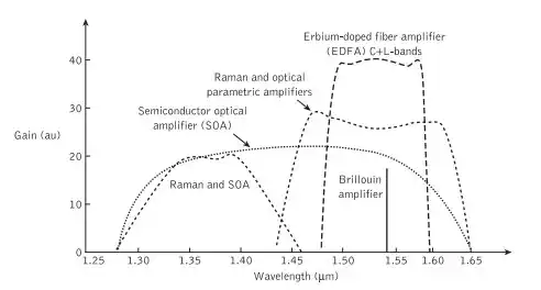
- Semiconductor optical amplifier (SOA)
- Raman Fiber amplifier (RFA)
- Erbium doped fiber amplifier (EDFA)
Semiconductor optical amplifier (SOA)
-
SOA is small in size
-
It provides amplification using stimulated emission, which is similar to Laser. But in case of Laser, amplification of light takes place when light beam carries many reflections between two faces.
-
In case of SOA, the amplification action takes place without many reflections.
Raman Fiber amplifier (RFA)
This type of amplifier works on the principle called SRS (Stimulated Raman Scattering)
When an atom is in the ground state and it absorb photon energy, it moves to the excited state. After reaching the excited state, it goes back to the ground state.
The energy that comes from the excited state down to the ground state is different from the original photon. The difference in energy level is caused by vibration in the fiber.
EDFA Erbium Doped Fiber Amplifier (EDFA)
Among the listed amplifiers, EDFAs is mostly used to compensate for loss in an optical fiber (most commonly telecommunication optical fibers) in a long-haul or long distance optical communication.
EDFA was invented in 1987 in which before that optoelectronic repeaters are used by a Prof. David Payne and his team EDF utilizes Erbium element as it has an important property.
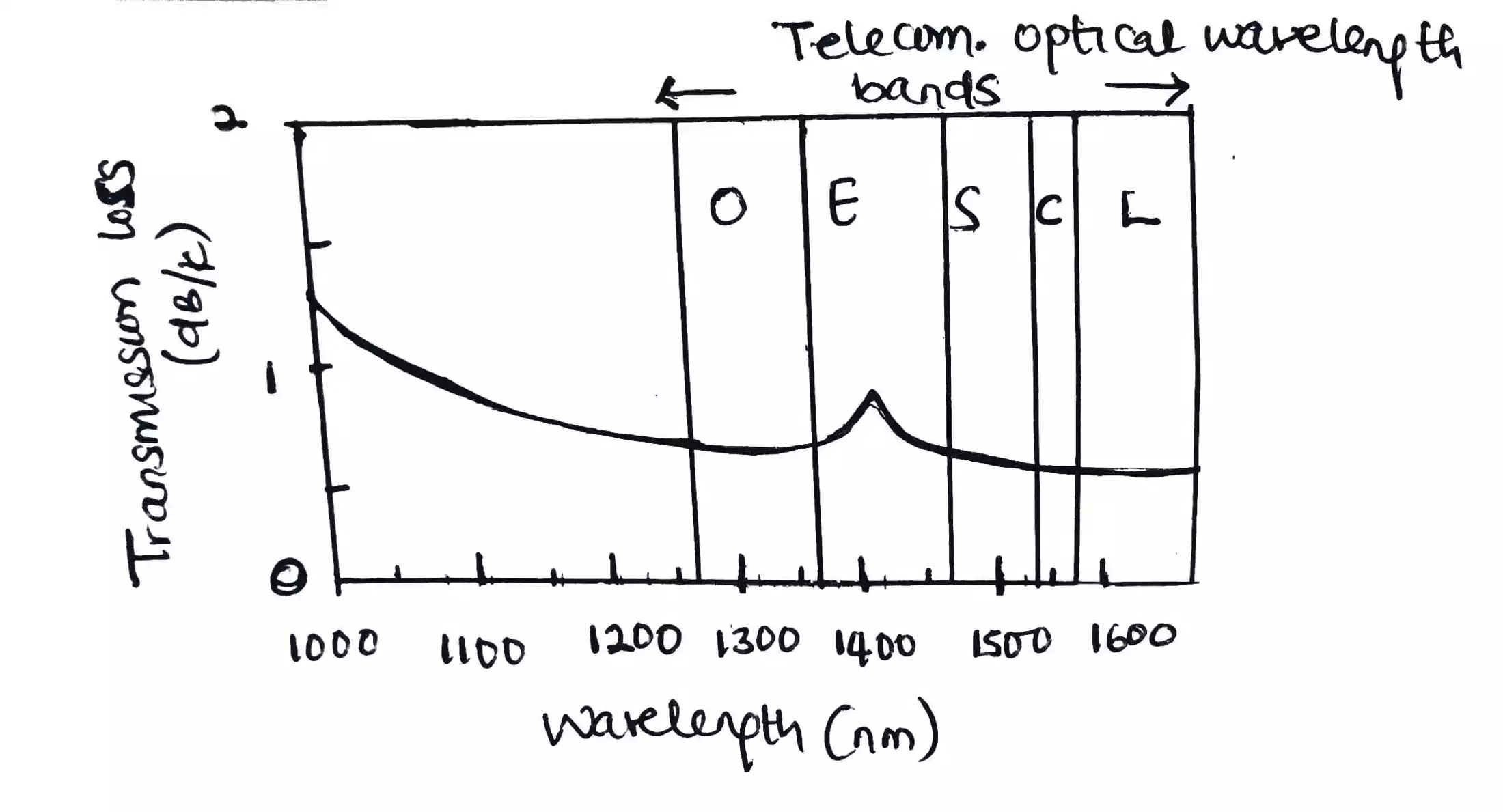
EDFA is used in the C band and L band where loss in telecommunication optical fiber becomes less in the entire optical telecom wavelength band.
Working principle of EDFA
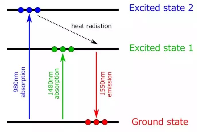
The figure below illustrates a simplified energy diagram of Er, showing how amplification takes place at 1550nm. Two typical wavelengths to pump an EDFA are 980nm or 1480nm.
Energy diagram of Er
source: slideshare
When an EDFA is pumped at 1489nm, Er ion doped in the fiber absorbs the pump light and is excited to an excited state (which is Excited state 1 in the diagram).
When sufficient pump power is launched to the fiber and population inversion is created between the ground state and excited state 1, amplification by stimulated emission takes place at around 1550nm.
Still when an EDFA is pumped at 980nm, Er ion absorbs the pump light and is excited to another state (which is excited state 2).
The lifetime of the excited state 2 is relatively short, and as a result, the Er ion is immediately relaxed to the excited state 1 by radiating heat.
This relaxation process creates a population inversion between the ground level and excited state 1, and amplification takes place at around 1550nm.
EDFA Configuration
EDFA Architecture
.webp)
Normally the pump light is injected in the same direction as the signal flow which is termed as co –directional pumping.
It is also possible to inject the pump power in the opposite to the signal flow and it is known as counter directional pumping.
Also, the pump light can be injected in both direction and it is known as dual pumping.
Counter directional pumping allows higher gains, but co-directional gives better performance
Characteristics of EDFA
EDFA is mostly used due to some of its characteristics;
-
It can be used to amplify multiple optical signal simultaneously and because of this can be used with wavelength division multiplexing (WDM) technology.
-
It can be used as a booster, inline and pre-amplifier in an optical transmission line.
-
Typical distance between each EDF amplifier is several tens of kilometers.
-
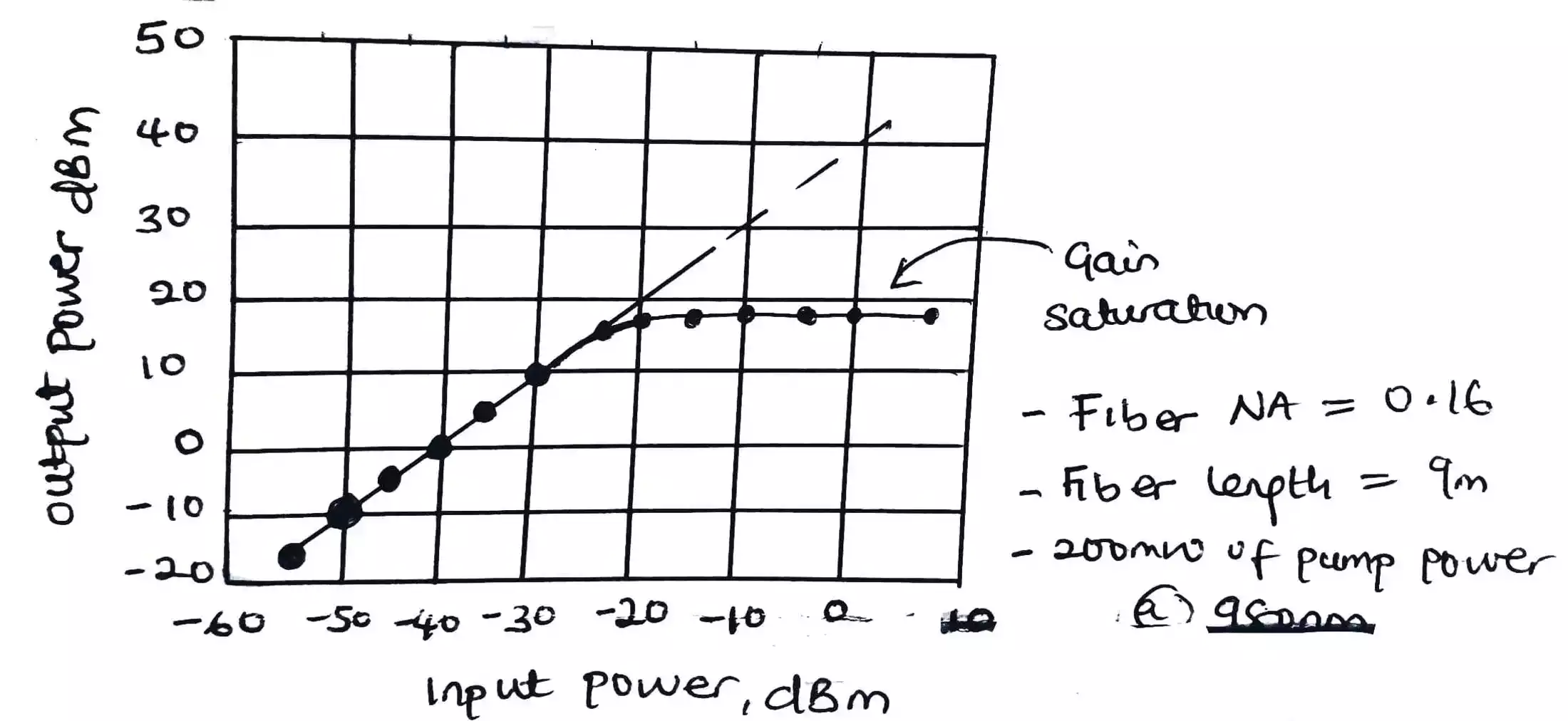
Saturated output power (or simply maximum output power)
Saturated output power is the maximum output power from an amplifier when sufficient signal input power (typically around 0 dBm or higher) is launched to the amplifier. A booster amplifier typically operates under this condition, and thus saturated output power is an important characteristic for a booster amplifier.
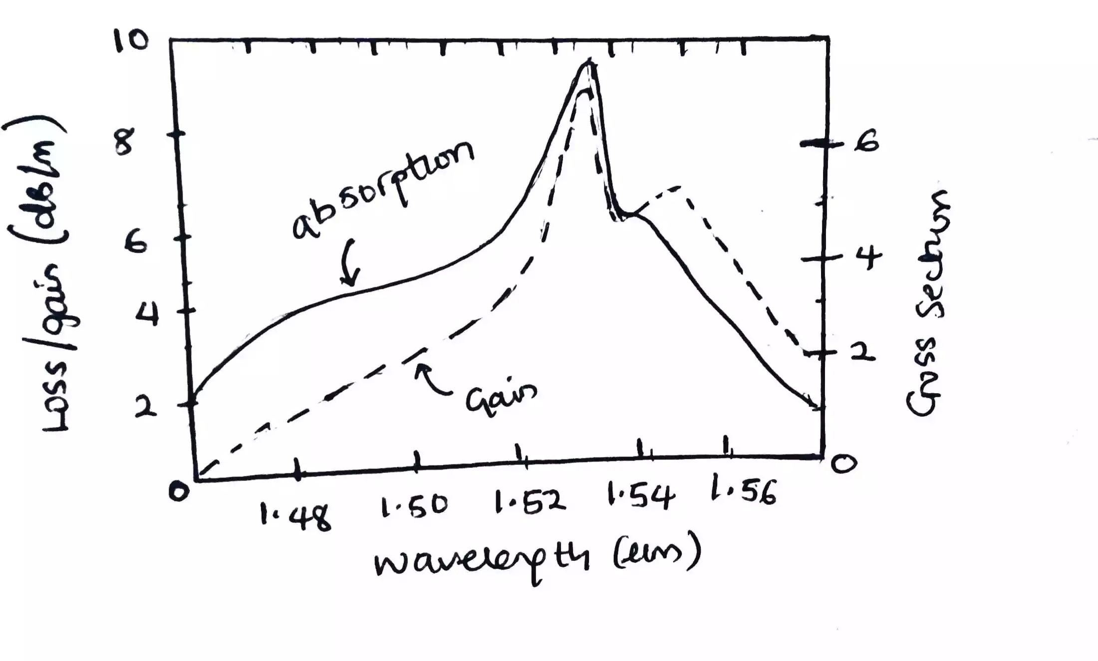
LOSS-GAIN CHARACTERISTICS
INPUT-OUTPUT CHARACTERISTICS
Advantages of EDFA
- Commercially available in C and L band
- High gain
- Low noise figure: 4.5dB to 6dB
- Immunity to crosstalk among WDM channels
- Do not require high speed electronics
- Simultaneous amplification of WDM signals
Disadvantages of EDFA
- Pump laser is necessary
- Difficult to integrate with other components