The 7 Logic Gates (AND, OR, NOT, NAND, NOR, XOR and XNOR) Explained With Their Truth Table

Logic gates are electronic circuits or devices that forms the basic building block for combinational circuits. It can be used to implement boolean expressions such as addition, subtraction etc.
There are no digital circuits without a logic gate. The logic gates are termed logic gate as they perform some logic function by either comparing input signals, adding, subtracting, multiplying etc. of input signal and then resulting in an output signal.
Logic gates understand zero’s (0’s) and one’s (1’s) or HIGH and LOW.
Logic gates mostly have at least two input terminal and one output terminal with an exception of the NOT gate which has one input and output terminal.
Types of logic gates
There are basically seven types of logic gate:
- NOT gate
- AND gate
- OR gate
- NAND gate
- NOR gate
- XOR gate and
- XNOR gate
Among these logic gates, some are universal while others are basic. The term universal gate is derived from the idea that operations that can be performed with the basic logic gates such as AND, OR, and NOT can be performed with just a single logic gate.
The universal logic gates are two: NAND (NOT – AND) and NOR (NOT – OR).
While XOR (exclusive OR) and XNOR (exclusive NOR) are logic gates that has the combination of some AND, OR or NOT gate, they are not universal but are used to reduce the number of gates in a circuit.
Before discussing on each logic gates, their symbol, function and truth table, we have to explain some basic terms.
The truth table is the table that tells how different input to a logic gate yields an output. In essence it is a table showing the relationship between the input signal and the output signal.
NOT gate
A NOT gate is a basic logic gate which is used to perform an inversion or complementation.
Symbol of a NOT gate

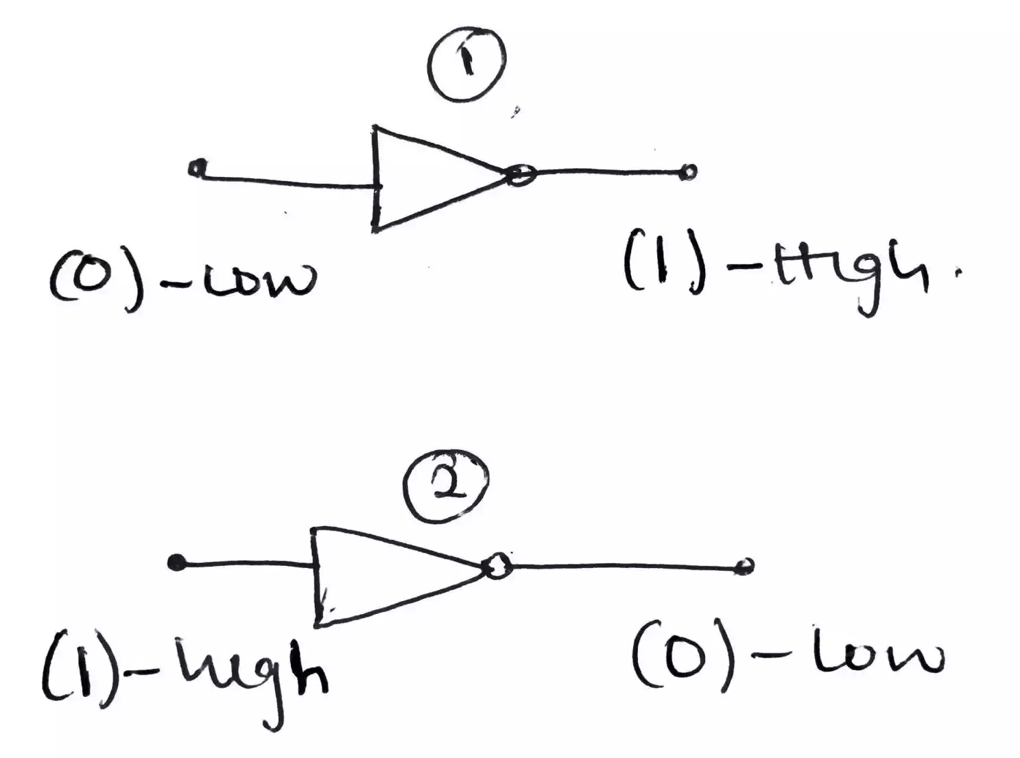
Operation of a NOT gate
A NOT gate is used to invert the input applied to it i.e. when a HIGH is applied at the input it results in a LOW and when a LOW is applied to the input it results in a HIGH.
Truth table - For a NOT gate
| Input | Output |
|---|---|
| 1 | 0 |
| 0 | 1 |
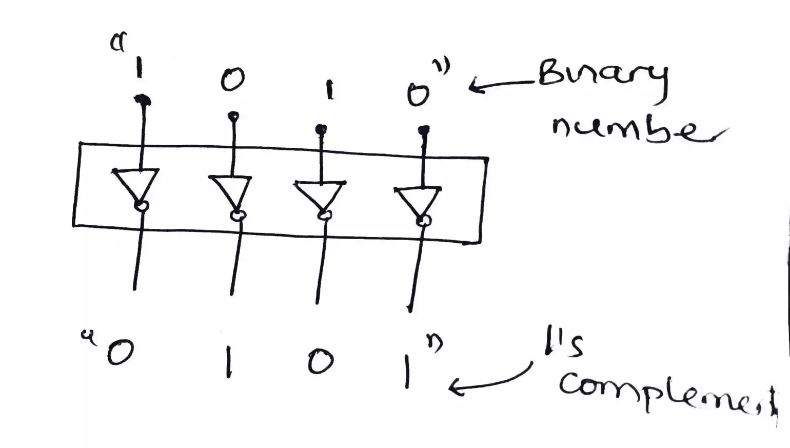
Application of a NOT gate
It can be used to construct a circuit which produces 1’s complement of an 4-bit binary number. The bit is applied to the input of the NOT gate and a resulting 1’s complement is available at the output.
AND gate
An AND gate is a basic logic gate which is used to perform an AND operation or logical multiplication.
Symbol of an AND gate
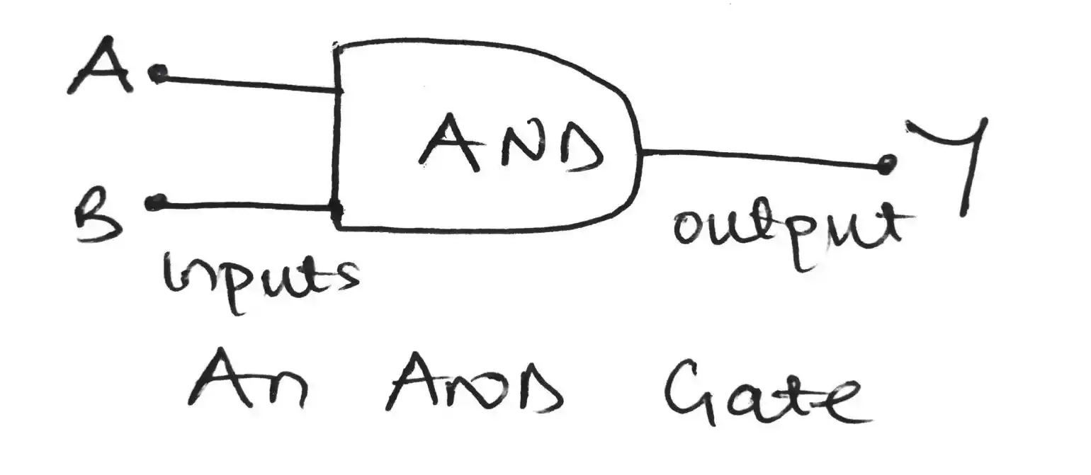
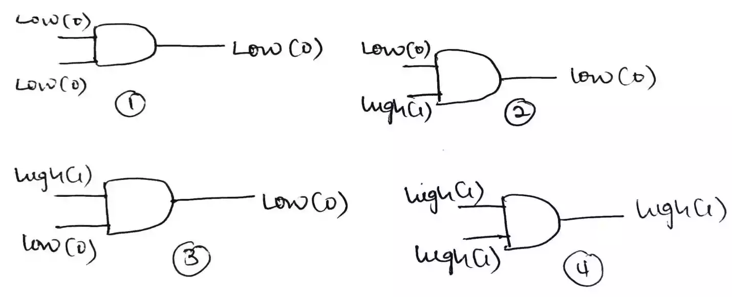
Operation of an AND Gate
The way an AND gate operates is quite similar to the normal multiplication we are familiar with, as any value multiplied by one results in that value also, any value multiplied by zero results in zero.
Furthermore, An AND gate produces a HIGH output only when all of the inputs are HIGH. When any of the inputs is LOW, the output is LOW.
Therefore, the purpose of an AND gate can be said to check when a certain condition is simultaneously HIGH so it produce a HIGH.
Truth table - For a 2 input AND gate
| Input A | Input B | Output Y |
|---|---|---|
| 0 | 0 | 0 |
| 0 | 1 | 0 |
| 1 | 0 | 0 |
| 1 | 1 | 1 |
Application of an AND gate
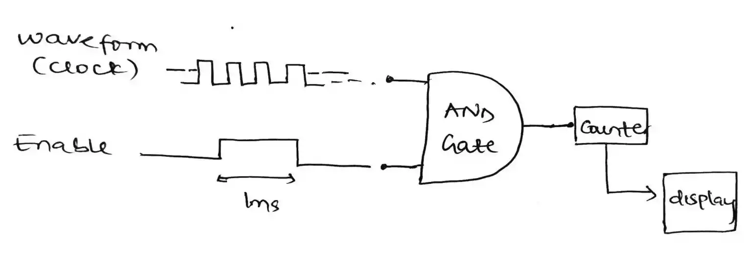
It can be used to make an Enable/Inhibit i.e. to allow the flow or passage of pulse signal from one point to another for a certain amount of time to prevent the passage of flow of pulse signal at other times).
The function of an AND gate in this case is to output a HIGH when the clock signal is applied and the enable signal is also HIGH. If the enable is off, then there will be no clock to clock the counter.
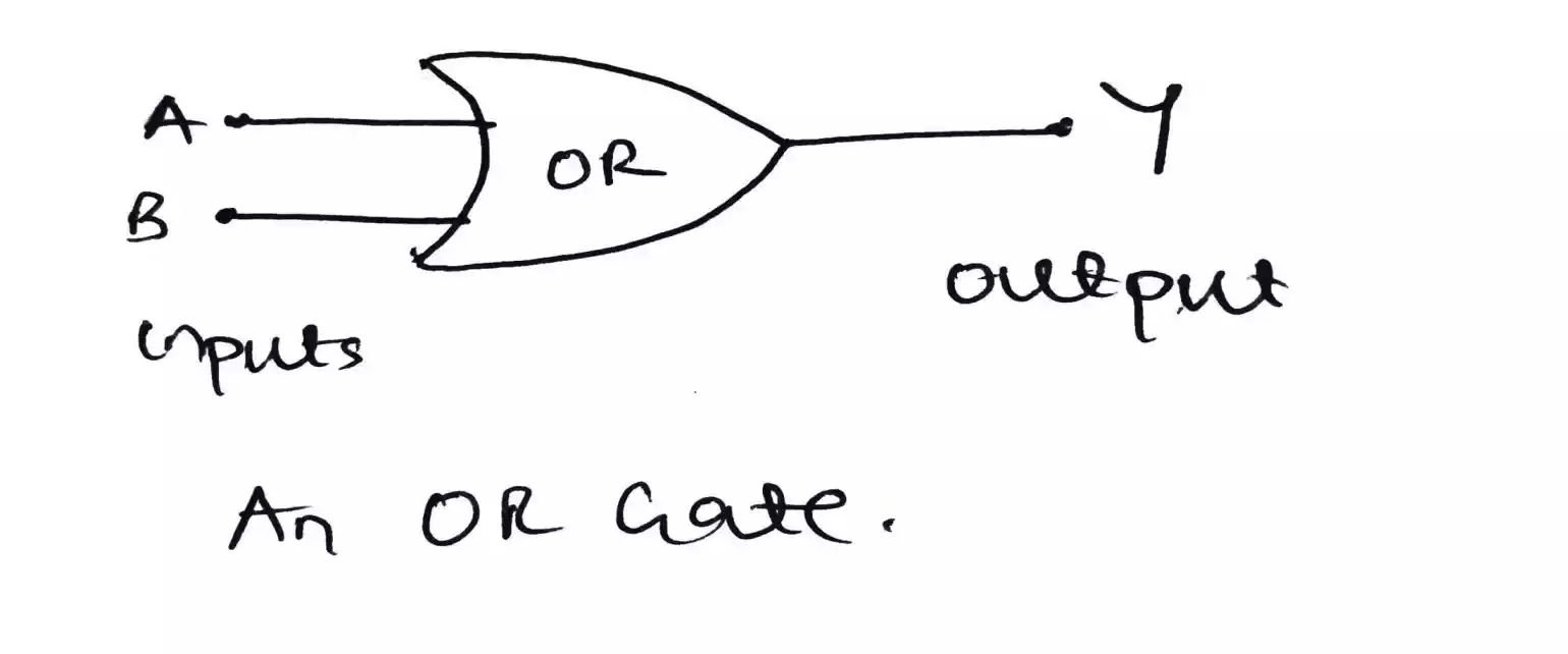
OR gate
An OR gate is another basic logic gate which is used to perform an OR operation or logical addition.
Symbol of an OR gate
Operation of an OR Gate
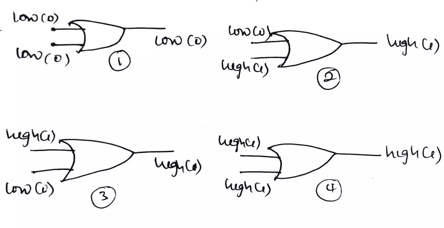
The way an OR gate operates is similar to normal addition but in this case its addition is with logical Booleans. i.e. if a one is added to another one it results in one. Also, if a one is added to a zero it yields a one.
Furthermore, An OR gate produces a HIGH output if any of its input is HIGH but will produce a LOW only if all its input is LOW
Truth table - For a 2 input OR gate
| Input A | Input B | Output Y |
|---|---|---|
| 0 | 0 | 0 |
| 0 | 1 | 1 |
| 1 | 0 | 1 |
| 1 | 1 | 1 |
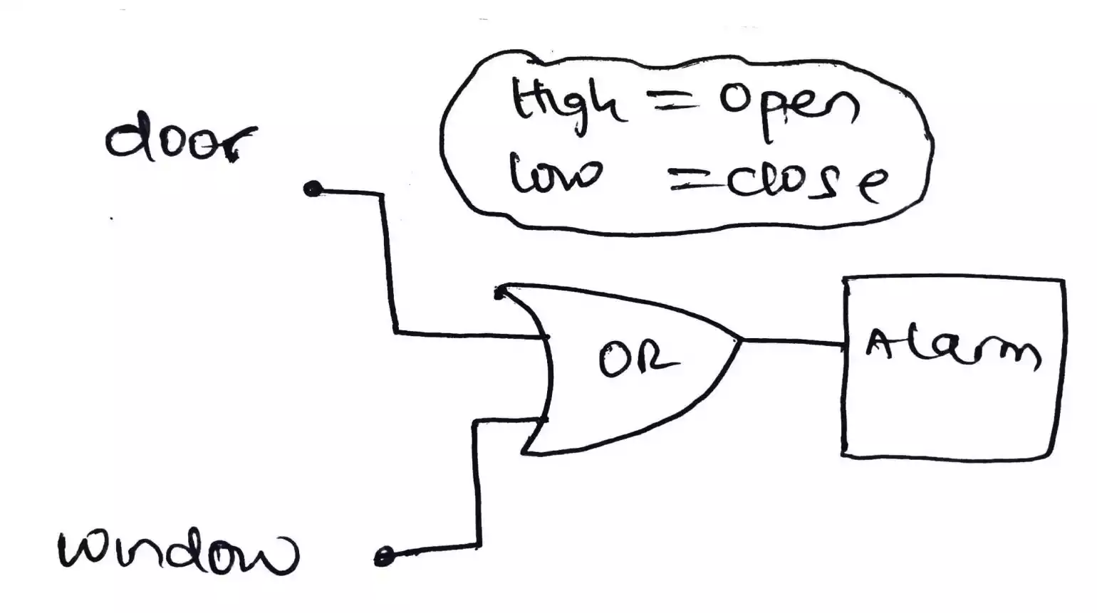
Application of an OR gate
It can be used in simple intrusion detection and alarm system. The OR gate can be used to check if either the door or the window is open.
If it is open, it results in a HIGH which will in turn trigger the alarm but if both the door and the window is closed then the output of the OR gate will be LOW which means that the alarm will not be triggered.
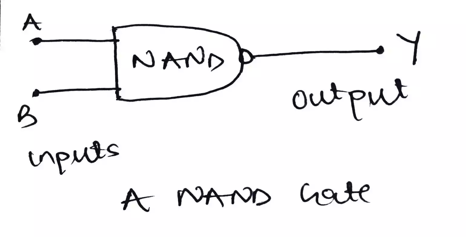
NAND gate
A NAND gate is a contraction of the word (NOT-AND). It is a universal gate and can be used to perform an AND, OR and NOT operations.
Symbol of a NAND gate
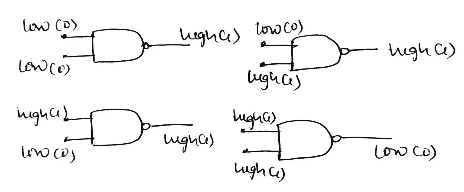
Operation of a NAND gate
The operation of a NAND gate is just an opposite of an AND gate. In other words, the output of an AND gate which is inverted is the output of a NAND gate.
If both inputs of a NAND gate is HIGH, it outputs a LOW while if one or all of its input is LOW, it outputs a HIGH.
Truth table - For a 2 input NAND gate
| Input A | Input B | Output Y |
|---|---|---|
| 0 | 0 | 1 |
| 0 | 1 | 1 |
| 1 | 0 | 1 |
| 1 | 1 | 0 |
Application of a NAND gate
It can be used to sense if the available water in a tank is below threshold. If it is below threshold i.e. one of the tank is LOW the output of the gate will be HIGH which will then trigger the alarm.
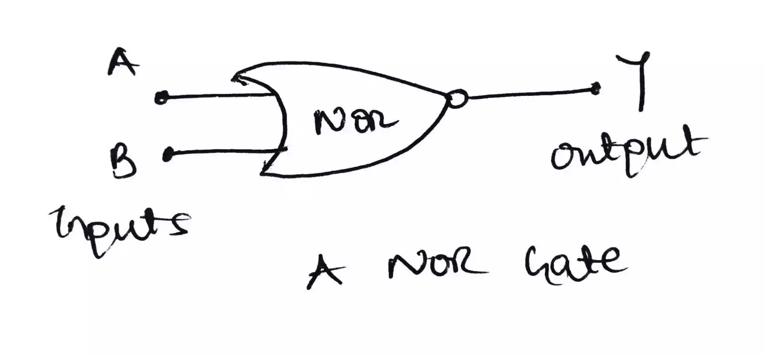
NOR gate
The NOR gate is also a universal gate as it can be used for performing an AND, OR and NOT operations.
Symbol of a NOR gate
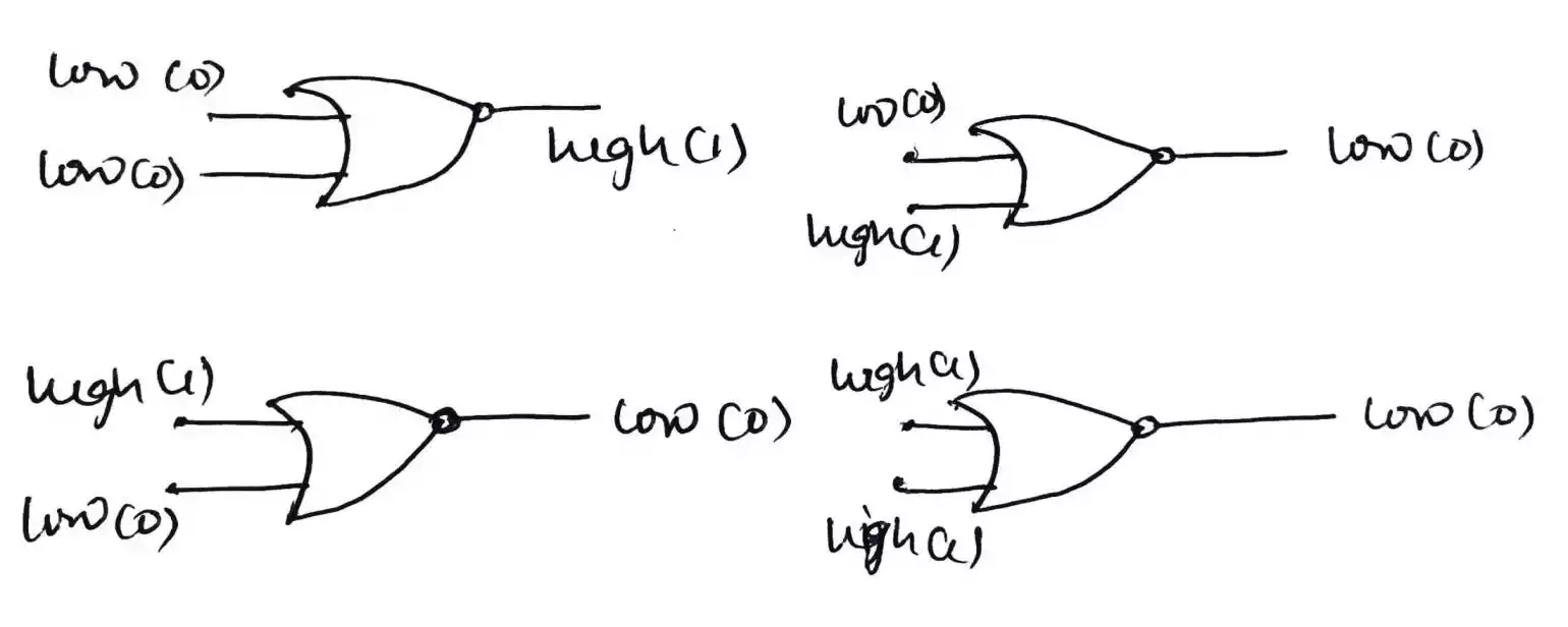
Operation of a NOR gate
Just as the NAND gate and the AND gate, a NOR gate’s output is opposite to that of the OR gate.
i.e. if any of the input is HIGH, a LOW is outputted but if all the input is LOW then it will output a HIGH.
Truth table - For a 2 input NOR gate
| Input A | Input B | Output Y |
|---|---|---|
| 0 | 0 | 1 |
| 0 | 1 | 0 |
| 1 | 0 | 0 |
| 1 | 1 | 0 |
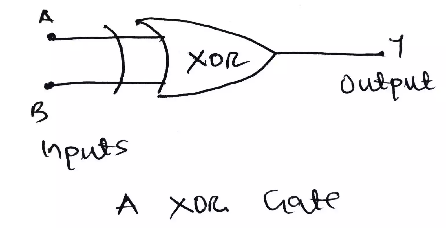
XOR (Exclusive OR) Gate
A XOR gate is a logic gate which is formed from the combination of other gates.
Symbol of a XOR gate
Operations of a XOR gate
When both inputs are different (i.e. HIGH and LOW or vice-versa) the output will be HIGH while if both inputs are same, it will output a LOW.
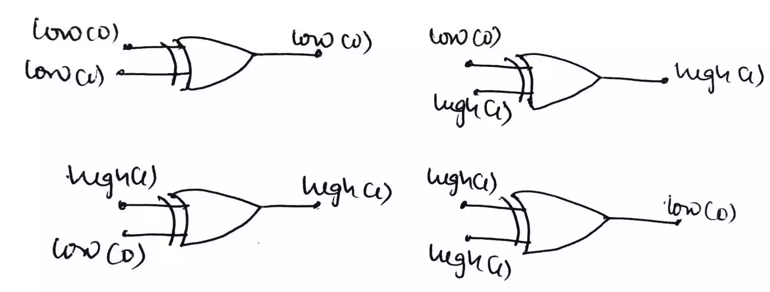
Truth table - For a 2 input XOR gate
| Input A | Input B | Output Y |
|---|---|---|
| 0 | 0 | 0 |
| 0 | 1 | 1 |
| 1 | 0 | 1 |
| 1 | 1 | 0 |
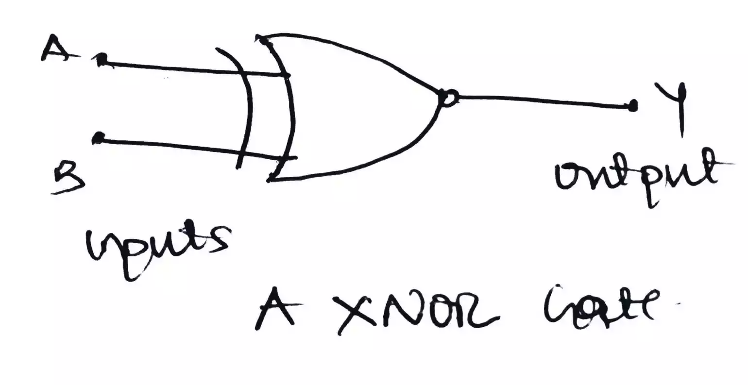
XNOR (Exclusive NOR) Gate
A XNOR gate is a logic gate which is also formed from the combination of other gates.
Symbol of a XNOR gate
Operations of a XNOR gate
The output of a XNOR is an opposite to the output of a XOR gate.
When both inputs are different (i.e. HIGH and LOW or vice versa) the output will be LOW while if both inputs are same, it will output a HIGH.
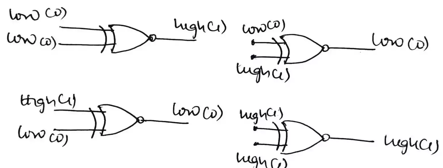
Truth table - For a 2 input XNOR gate
| Input A | Input B | Output Y |
|---|---|---|
| 0 | 0 | 1 |
| 0 | 1 | 0 |
| 1 | 0 | 0 |
| 1 | 1 | 1 |